Emitter follower in the IF stage of Universal Receiver
While watching the superhetrodyne 101 video series of Chuck Adams, K7QO on youtube, the Emitter follower circuit after the IF mixer stage (before the IF crystal filter stage) caught my attention. I studied electronics in college back in 1994-1998 time frame, so it is 20 years since I passed out of college. I was not fortunate to have good teachers for circuits, but we had a fairly good library and I remembered some parts of the electronics I studied with the Millman and Halkias book.
One of the things that baffled me about real world circuits and text book ones is on how values are arrived at. Most circuit designers never tell us how they arrived at the values. After I started using the internet (back when I was in college, we never had access to the Internet), I got to know about various better text books. One of them being "The electronics of Radio" which uses the Norcal 40A QRP Transceiver to explain the theory and practice. But Chuck's explanation of Universal Receiver is even better! Universal Receiver is also simpler and can be a great lab course for college students.
So let us see the circuit after the IF mixer stage of the Universal Receiver from W8DIZ, the subject of Chuck's video series. Universal receiver is one which one can call as a completely understandable circuit (in the lines of good old Unix v6/v8 or Plan 9). It is small and has well defined parts and as Chuck demonstrates, it is completely comprehensible for anyone with some knowledge of electronics. Still there are a few things that elude me.
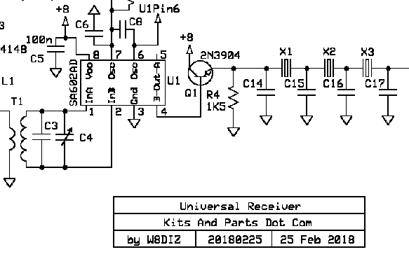
So, Q1 is our emitter follower circuit. It is called "emitter follower" because, the voltage across the load, R4, "follows" the base voltage. Why? Because:
Voltage at the base - Voltage drop across Base-Emitter junction = Voltage at Emitter.
The Vbe is around 0.6v, so Ve ≅ Vb.
Why would anyone use such a circuit? Though voltage gain is unity, this circuit has a current gain, which intuitively implies, more current flows in the output load of this circuit than input and that translates into a high input impedance and a low output impedance.
So, we use an emitter follower whenever we need to pipe the output of one block with a high impedance to another block with a different low input impedance. In this case, the SA602/NE612 has an output impedance of 1.5kΩ at pin 4. The input impedance of the crystal filter is say, around 150Ω (I am quoting Chuck. I haven't computer it from the above circuit). We have an emitter resistor of value 1.5kΩ, so the emitter current = 8 Volts/1.5KΩ = 5.33 mA. The transistor small signal gain for 2n3904 for a collector current of 5mA is between 80 and 100. Let us assume 100 for our calculations.
From the book, The Art of Electronics:
Zout = Re || [(Zin || input bias resistors)/h_fe ]
where Zin is the output impedance of the circuit driving the emitter follower (1.5kΩ), Re is also 1.5kΩ. There is a 1.5kΩ internal bias resistor on Pin 4 of SE602. So, in this case, Zout = (1.5kΩ || [(1.5kΩ || 1.5kΩ)/100], which is around 7.5Ω ? The second part of the parallel reistence is always low, owing to the division, so overall resistance is dictated by it, given the fact that Re is usually high?
That looks too low to me. Where did I go wrong?